Modbus Simulator
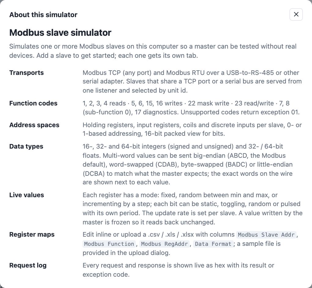
A Modbus slave on your own machine: TCP, RTU or ASCII, with the register map, data types, byte order and value behaviour of the device you are developing against. This is the simulator's user guide.
What the simulator does
The simulator makes your PC behave like one or more Modbus slave devices, so a Modbus master — a SCADA system, gateway, PLC, data logger or your own firmware — can be developed and tested without the real equipment.
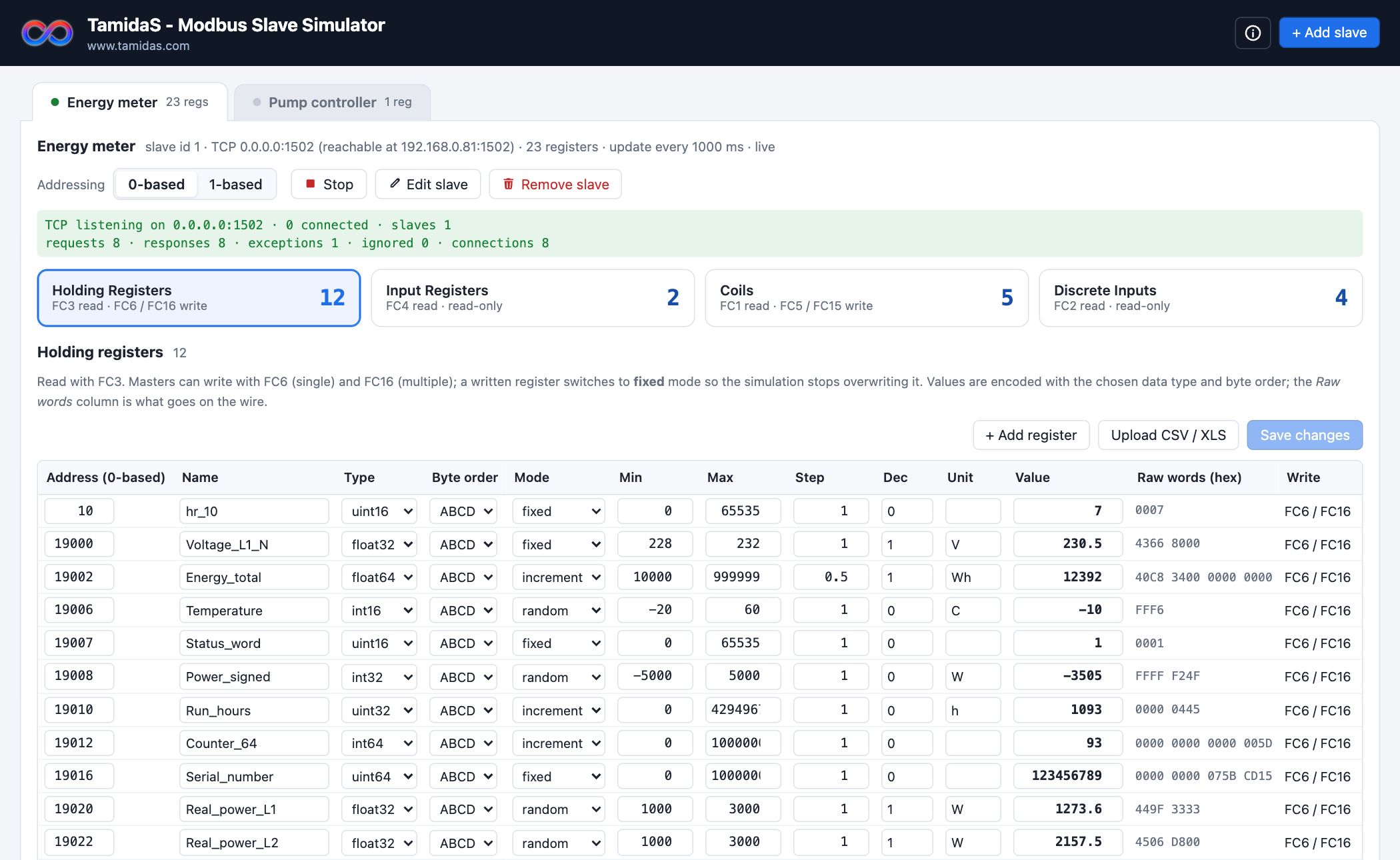
- Three protocols. Modbus TCP on any port, and Modbus RTU or Modbus ASCII over a serial line such as a USB-to-RS-485 adapter.
- Any number of slaves. Each slave has its own name, slave id, protocol and register map. Slaves can share a TCP port or a serial bus.
- All four address spaces. Holding registers, input registers, coils and discrete inputs.
- Function codes 1, 2, 3, 4, 5, 6, 7, 8, 15, 16, 17, 22, 23 and 43/14 (device identification), with correct exception responses for everything else.
- Realistic data. Integers and floats in any byte order, values that change by themselves, counters that increment, coils that toggle or pulse.
- Register maps from files. Upload a CSV or Excel register list; a template is included.
- Full visibility. Every request and response is logged as hex with its result.
Getting started
- Run the program. On Windows double-click
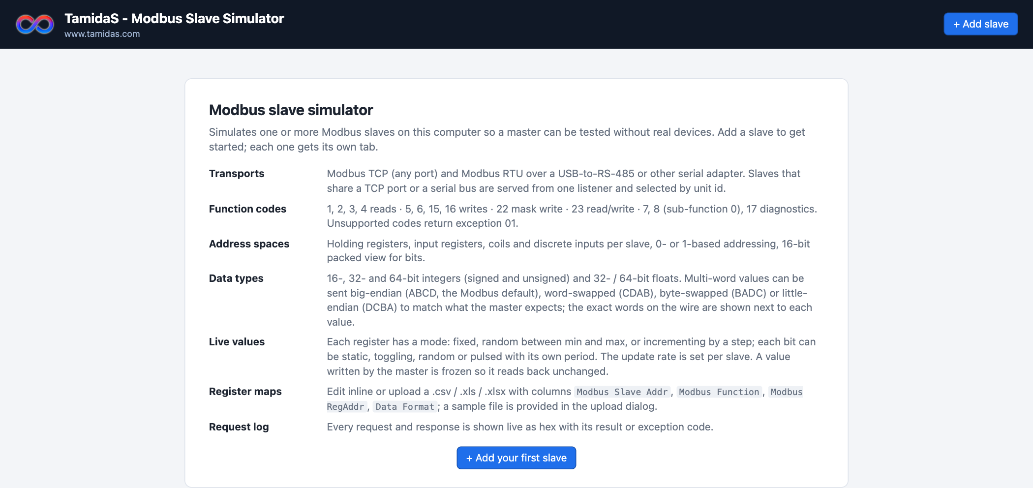
tamidas-modbus-simulator.exe; on macOS or Linux unpack the.tar.gzand start the binary from a terminal (see Command line for the first-run notes). A console window opens and shows the web address, and your default browser opens the simulator. Keep the console window open; closing it stops the simulator. - Add a slave. On first start there are no slaves yet and the page shows an overview. Click + Add slave in the header (or the button in the overview) and follow Adding a slave.
- Load a register map. Upload the device's register list (see Importing a register map) or add registers by hand.
- Connect your master to the address shown in the slave tab and start polling. Watch the request log.
data folder created next to the executable, so everything is back after a restart. Copy the executable to another folder to keep a separate setup.How data flows between master and simulator
A Modbus master sends a request; the simulator answers on behalf of the slave whose id is in the request. The pictures below show that exchange for Modbus TCP and for Modbus RTU, and what happens inside the simulator in between.
Modbus TCP
The master opens a TCP connection to the simulator PC's address and port and sends requests over it. One listener serves every slave on that port; the unit id byte in each request selects the slave.
- The master needs three things: the simulator PC's IP address (shown in the slave tab), the port, and the unit id equal to the slave id.
- Several masters can be connected at the same time; each connection is served independently.
- Slaves on different ports get their own listener; slaves on the same host and port share one.
Modbus RTU
With RTU there is no network: the master and the simulator PC are joined by a two-wire RS-485 bus through a USB adapter. Frames are raw bytes with a CRC, separated by silence, and the first byte is the slave address.
- Line settings (baud rate, data bits, parity, stop bits) must be identical on both ends, otherwise frames arrive corrupted and show as bad-crc in the log.
- Because the bus is shared, the master must wait for each response before sending the next request; the simulator replies immediately unless a response delay is configured.
- Several simulated slaves on one adapter behave like several physical devices on the bus.
Modbus ASCII
Modbus ASCII is the second transmission mode of the Modbus serial line. The wiring, the bus rules and the slave addressing are those of Modbus RTU; what changes is how a frame is written on the wire. Every byte is sent as two readable hexadecimal characters, a frame starts with a colon and ends with carriage return + line feed, and the checksum is an 8-bit LRC instead of the CRC-16. Older PLCs, some drives and devices behind modems or radio links use it because it tolerates long pauses between characters.
- A frame begins at
:and ends at CR LF. A new colon always restarts reception, so a master that aborts a frame and starts again is understood. - Characters may arrive up to 1 second apart. A longer gap discards the partial frame, which is logged as bad-lrc.
- The standard line setting is 7 data bits, even parity, 1 stop bit (7E1), because only ASCII characters travel on the line; many devices also allow 7O1, 7N2 or 8N1. It must match the master.
- Frames with a wrong LRC, an odd number of hex characters or non-hex characters are not answered and show as bad-lrc in the log. Lowercase hex is accepted; responses use uppercase.
- A frame is about twice as long as in RTU, so polling is slower at the same baud rate.
- RTU and ASCII cannot be mixed on one bus: every device on a serial port uses the same mode. Slave address 0 is a broadcast — processed, never answered — exactly as in RTU.
Inside the simulator
Whichever transport delivered the frame, the same steps produce the answer:
| Step | What can go wrong | Seen as |
|---|---|---|
| 2 · Parse | Wrong baud rate or parity, noise on the bus | bad-crc in the log, no reply |
| 3 · Route | Master uses a slave id that is not hosted on that port or bus | ignored in the log, no reply — the master times out |
| 4 · Execute | Unsupported function, undefined address, bad quantity | exception 01 / 02 / 03 |
| 5 · Encode | Byte order or type differs from what the master expects | reply is ok but the master shows a wrong value — compare with the Raw words column |
Slaves
A slave is one simulated device. Every slave appears as a tab named after it.
Adding a slave
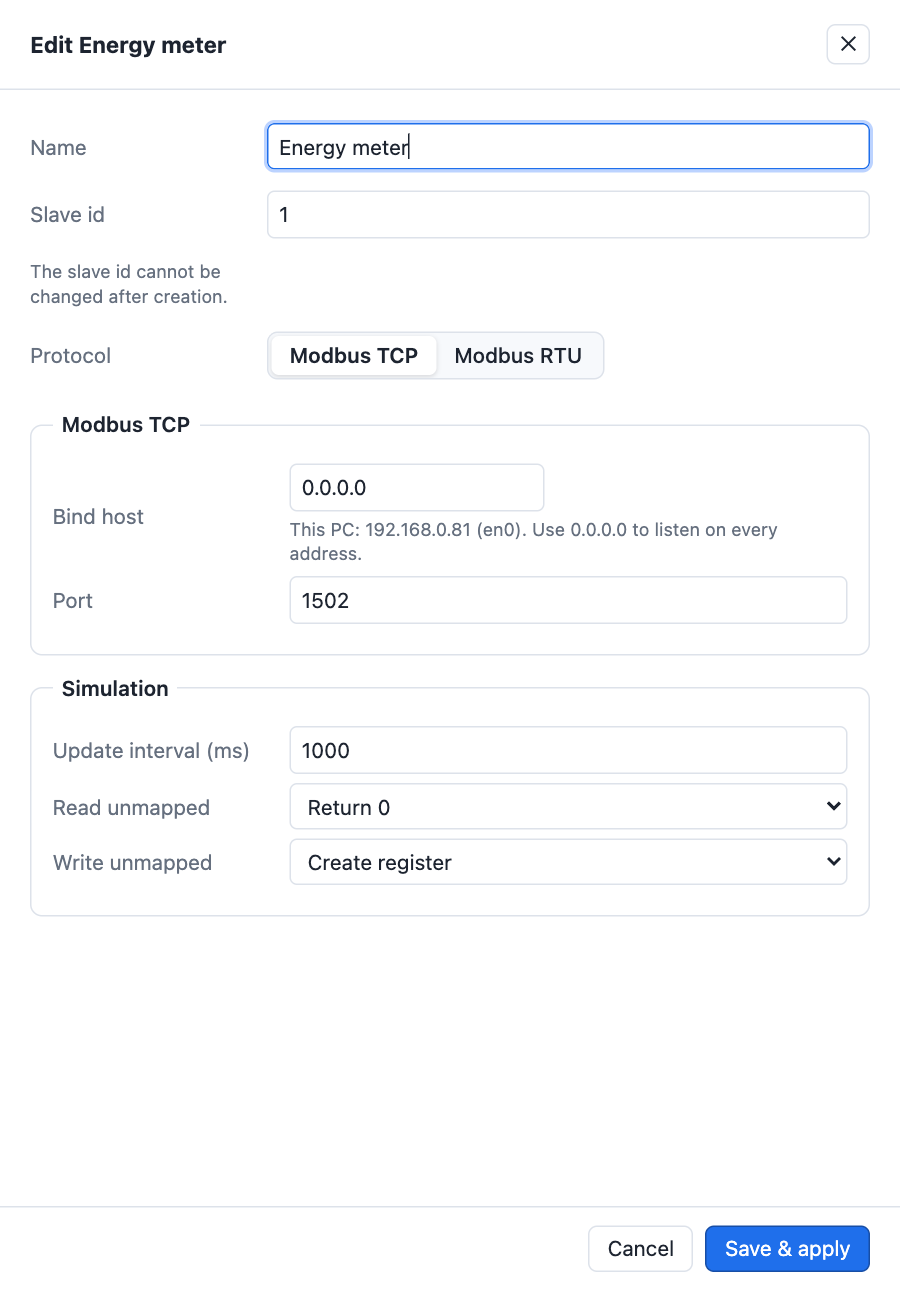
Click + Add slave. A panel slides in from the right.
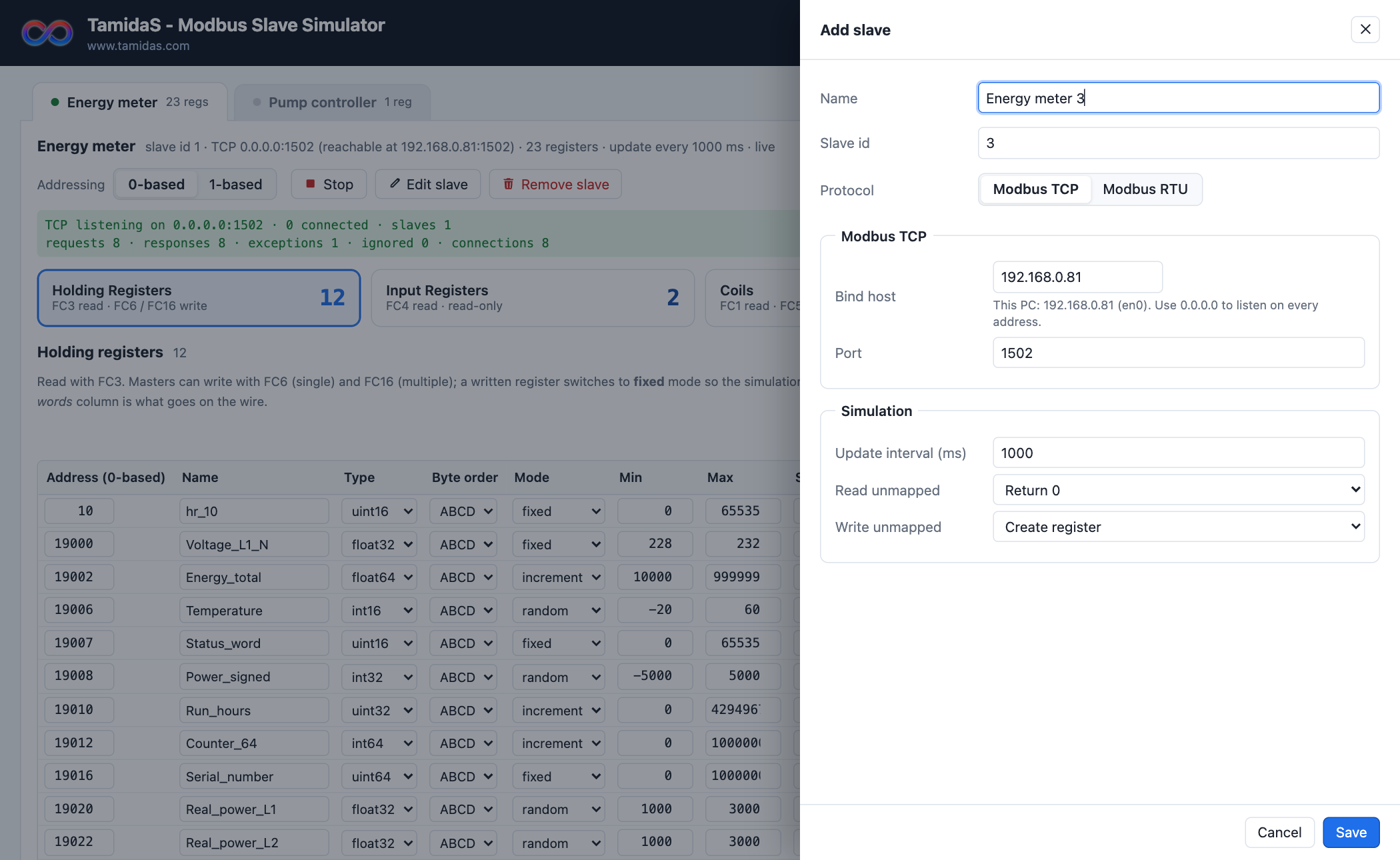
| Field | Meaning |
|---|---|
| Name | Shown on the tab. Anything you like, for example the device model. |
| Slave id | The Modbus unit identifier the master will address, 1–247. The next free id is suggested. It cannot be changed later; remove and re-add the slave instead. |
| Protocol | Modbus TCP, Modbus RTU or Modbus ASCII. The settings below change with the choice. |
Press Save. The slave is created, its transport is started, and its tab opens. If the transport could not start — for example the port is in use — the slave is still created and the reason is shown in the tab.
Modbus TCP settings
| Field | Meaning |
|---|---|
| Bind host | The address the slave listens on. The simulator detects the PC's network addresses and prefills the LAN address; this is also the address to enter in the master. Choose 0.0.0.0 to listen on every address of the PC, or 127.0.0.1 to accept connections from this PC only. Click the field to pick from the list. |
| Port | TCP port, normally 502. No administrator rights are needed. Use another port if 502 is taken by other software. |
0.0.0.0 avoids that; the tab then shows the reachable address next to it.Modbus RTU settings
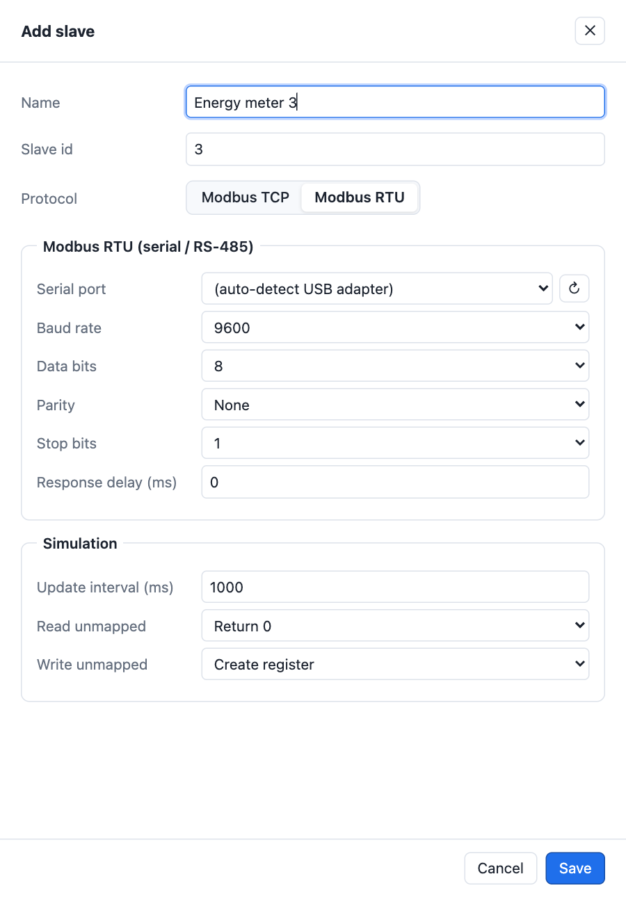
| Field | Meaning |
|---|---|
| Serial port | The COM port of the USB-to-RS-485 adapter (Windows COMx, macOS /dev/tty.usbserial-…, Linux /dev/ttyUSB0). Auto-detect USB adapter picks the first USB serial adapter found at start time. |
| Baud rate, Data bits, Parity, Stop bits | Must match the master exactly. Common meter settings are 9600 or 19200 baud, 8 data bits, no parity, 1 stop bit — written 9600 8N1. |
| Response delay (ms) | Extra pause before each response. Leave at 0 unless you are testing a master's timeout handling or a slow device. |
Modbus ASCII settings
A Modbus ASCII slave uses the same serial settings as an RTU slave — serial port, baud rate, data bits, parity, stop bits and response delay — with these differences:
| Field | Meaning |
|---|---|
| Data bits, Parity | Choosing Modbus ASCII switches the fields to the standard 7E1 (7 data bits, even parity, 1 stop bit) if they still hold the RTU default 8N1, and back again when you return to RTU. Change them if your master uses something else, for example 8N1 or 7O1. |
| Response delay (ms) | As for RTU. There is no silence requirement between ASCII frames, so 0 is fine for every master. |
Simulation settings
These settings are per slave and sit at the bottom of the Add / Edit panel.
| Setting | Meaning |
|---|---|
| Update interval (ms) | How often registers in random and increment mode get a new value. Bits have their own period (see Bit modes). |
| Read unmapped | What a master gets when it reads an address you have not defined. Return 0 makes block reads over gaps succeed, like most meters. Exception 02 rejects the whole read with illegal data address, like a strict device. |
| Write unmapped | What happens when a master writes to an undefined address. Create register adds a new holding register or coil at that address with the written value. Exception 02 rejects the write. |
| Device identification | What a master gets when it asks who the slave is with function code 43 / 14: vendor name, product code and revision, plus the vendor URL, product name, model name and application name. Each field has a default; the application name defaults to the slave's name. Clients such as the Modbus Logic Client show these next to the connection. |
The slave tab

- Tab strip. One tab per slave with a status dot: green when its transport is running, red when it failed, grey when stopped. The register count is shown next to the name.
- Summary line. Slave id, protocol and endpoint, number of registers, update interval and whether the transport is live.
- Addressing. Shows addresses 0-based or 1-based everywhere. See Addressing.
- ▶ Start / ■ Stop — one button that starts or stops this slave's transport. The label shows the action it will perform.
- ✎ Edit slave — opens the same panel as Add slave with the current values. Name, protocol, transport and simulation settings can all be changed; saving applies them and restarts the transport if it was running.
- 🗑 Remove slave — deletes the slave and all its registers after confirmation.
- Status line. Green while listening (with request counters for TCP), red with the reason when the transport could not start, hidden when stopped.

Several slaves at once
Add as many slaves as you need. How they share the hardware follows the Modbus rules:
- Same TCP port. Slaves with the same bind host and port share one listener. The unit id in each request selects the slave. A request whose unit id matches none of them — including 0 and 255 — is not answered and appears as ignored in the log, so set the master's unit id to the slave id.
- Different TCP ports. Each gets its own listener.
- Same serial port. Slaves with the same port, the same mode (RTU or ASCII) and identical line settings share the adapter, exactly like several devices on one RS-485 bus. Frames for other slave ids are ignored. If the line settings differ, the second slave is not started and shows a conflict message.
- TCP and RTU together are independent and can run side by side.
Address spaces
Each slave has the four Modbus address spaces. The cards at the top of the tab select which one the table shows and display the register count in each.

| Space | Read | Write | Content |
|---|---|---|---|
| Holding registers | FC3 | FC6 (one), FC16 (many), FC22, FC23 | 16-bit words; multi-word values span consecutive addresses |
| Input registers | FC4 | read-only | 16-bit words |
| Coils | FC1 | FC5 (one), FC15 (many) | single bits |
| Discrete inputs | FC2 | read-only | single bits |
Addresses are independent per space and per slave: holding register 0 and coil 0 are different things, and slave 1's register 100 has nothing to do with slave 2's.
Holding and input registers
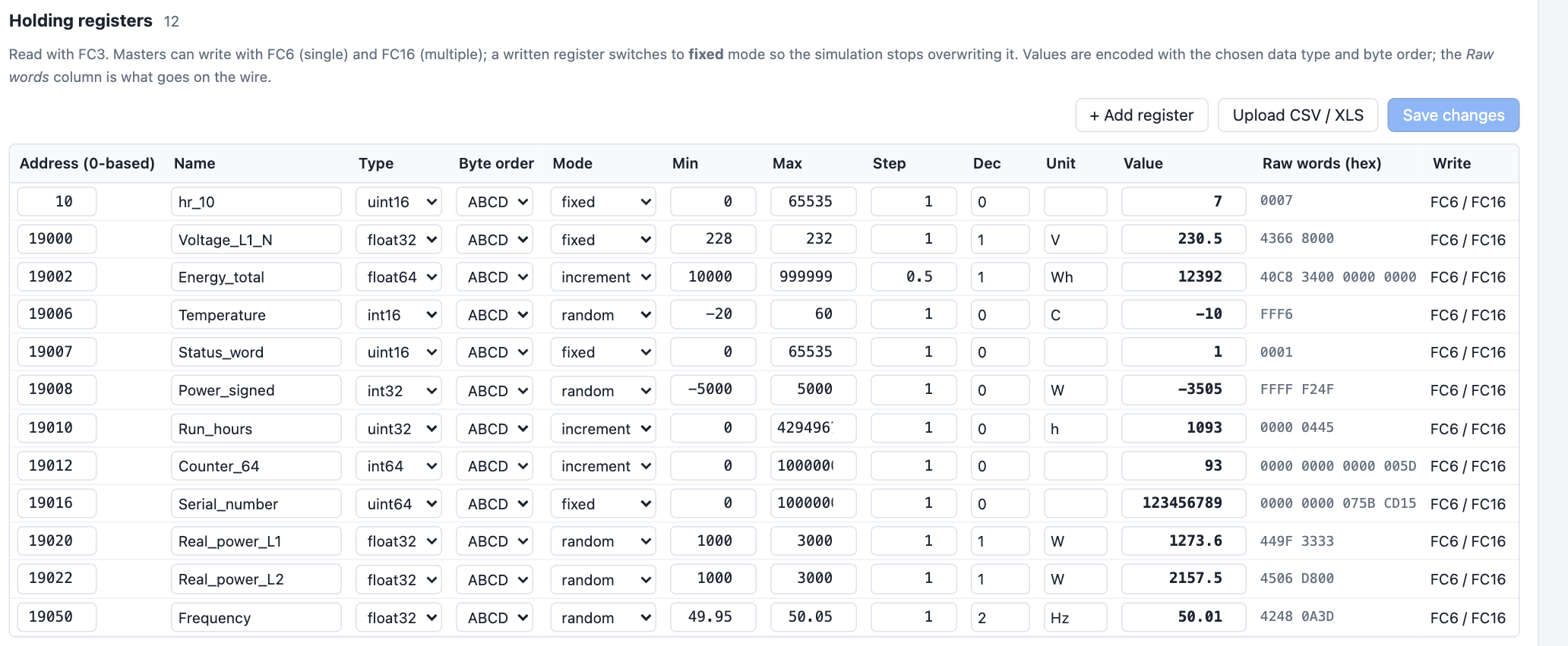
Table columns
| Column | Meaning |
|---|---|
| Address | Start address of the value. A 32-bit value occupies this address and the next one, a 64-bit value four addresses. Shown 0- or 1-based according to the addressing switch. |
| Name | Free text to identify the register. |
| Type | Data type, see below. |
| Byte order | How multi-word values are arranged, see below. |
| Mode | How the value changes over time, see Value modes. |
| Min / Max | Range for random mode and wrap-around limits for increment mode. |
| Step | Amount added on each update in increment mode. |
| Dec | Decimal places kept when generating values. |
| Unit | Engineering unit, for your reference only. |
| Value | The current value. Type a value to set it; the register switches to fixed so it stays. |
| Raw words (hex) | The 16-bit words exactly as they are sent to the master, after type conversion and byte ordering. |
| Write | Which function codes can write this space, or read-only. |
Data types and byte order
| Type | Words | Range |
|---|---|---|
int16 / uint16 | 1 | −32 768…32 767 / 0…65 535 |
int32 / uint32 | 2 | ±2.1 × 10⁹ / 0…4.29 × 10⁹ |
int64 / uint64 | 4 | 64-bit integers |
float32 | 2 | IEEE 754 single precision |
float64 | 4 | IEEE 754 double precision |
Modbus itself only knows 16-bit words, so devices differ in how they split larger values. The byte order column reproduces the device you are simulating. With the bytes of a 32-bit value called A B C D (A most significant):
| Byte order | Also called | Words on the wire |
|---|---|---|
ABCD | big-endian, "Modbus standard" | AB CD |
CDAB | word-swapped, little-endian words | CD AB |
BADC | byte-swapped | BA DC |
DCBA | little-endian | DC BA |
4366 8000 in ABCD and 8000 4366 in CDAB.Value modes
| Mode | Behaviour |
|---|---|
| fixed | The value never changes by itself. Typing a value sets this mode automatically. |
| random | Every update interval a new value between Min and Max is generated, rounded to Dec decimals. Good for voltages, currents and temperatures. |
| increment | Every update interval Step is added. When the value passes Max it wraps to Min. Good for energy and run-hour counters. |
The update interval is a per-slave setting (see Simulation settings).
Editing, adding and deleting

- Editing. Change any cell directly in the table. Edited rows are highlighted and the Save changes button shows how many rows are pending. Press it, or Ctrl+S (⌘+S on a Mac), to apply them. Live values keep updating rows you are not editing.
- + Add register adds a row after the last one, at the next free address, copying the type and byte order of the previous row. Edit it and save.
- ✕ at the end of a row deletes it after confirmation. Deletion is immediate and does not need Save.
- Upload CSV / XLS imports a whole map, see Importing a register map.

Coils and discrete inputs
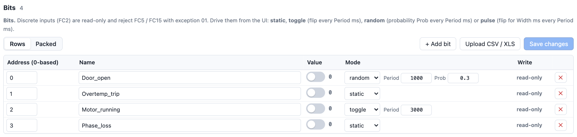
Coils (FC1) and discrete inputs (FC2) are single bits. Their table is simpler: an address, a name, a switch showing the current value, a mode with its parameters, and the write access.
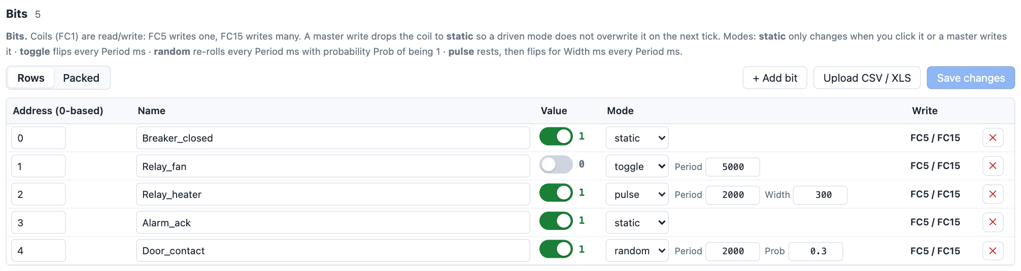
- Switch. Green with 1 means set, grey with 0 means clear. Clicking it changes the value at once; in a driven mode the new value is the starting point for the next cycle.
- + Add bit adds a bit at the next free address.
- Coils can be written by the master with FC5 and FC15; discrete inputs are read-only and reject those with exception 01.
Bit modes
Choosing a mode shows only the fields that mode uses.
| Mode | Parameters | Behaviour |
|---|---|---|
| static | — | Never changes by itself. Only a click or a master write changes it. Use it for inputs you want to control by hand. |
| toggle | Period | Flips every Period ms: a square wave with 50 % duty. Period 5000 gives a 10 s cycle. Simulates a running/stopped contact. |
| random | Period, Prob | Every Period ms the bit is re-rolled: it becomes 1 with probability Prob (0–1), otherwise 0. Prob 0.3 means set about 30 % of the time. |
| pulse | Period, Width | Rests at its current value, then flips to the opposite value for Width ms, every Period ms. Width 0 means one simulation tick. Simulates an alarm blip or a button press. |
Packed view
The Rows / Packed switch, available for coils and discrete inputs, shows the bits the way FC1 and FC2 return them: one 16-bit word per row with bit 0 on the right, and the word value in hex.
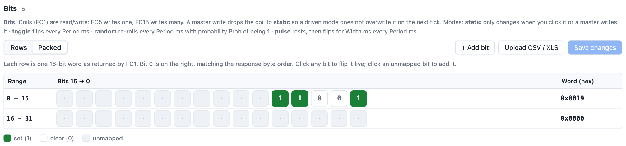
- Click a green or white cell to flip that bit.
- Click a grey cell to add a bit at that address.
- The Word (hex) column is what a master reading those 16 bits receives, which makes it easy to compare with a master's raw view.
0-based and 1-based addressing
Modbus frames carry 0-based addresses, but many manuals and masters number registers from 1, or use the 40001 / 30001 convention. The switch in the tab header changes how addresses are displayed everywhere for that slave: the tables, the packed view and the request log.
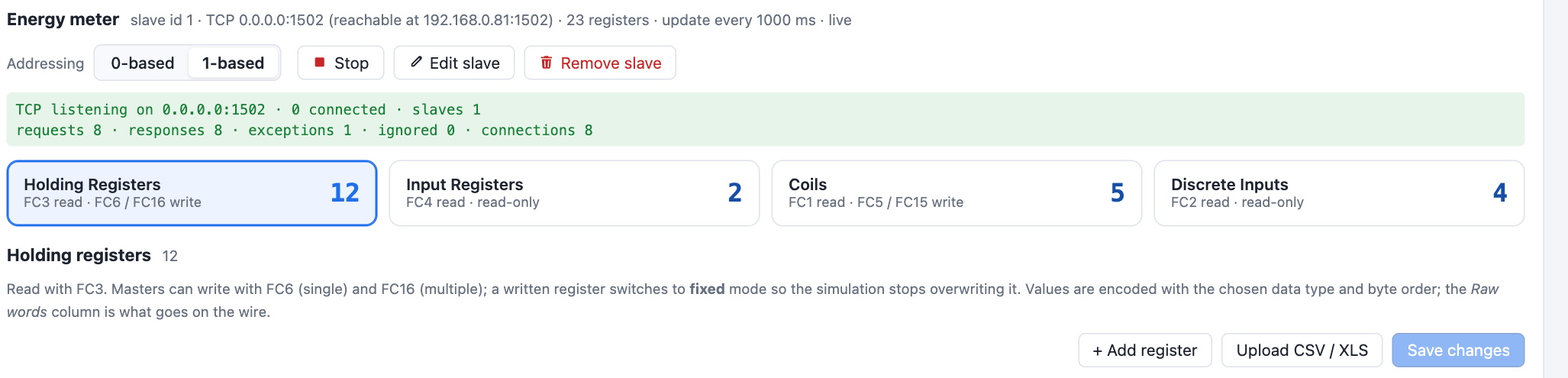
- The setting only affects what you see. Nothing changes on the wire.
- Values typed into the Address column are interpreted in the selected base.
- Import and export files always use 0-based protocol addresses.
- For the 40001 convention enter
40001in the master as register 1 (1-based) or 0 (0-based) here — the leading 4 only identifies the holding register space.
Writes from the master
Masters can write holding registers (FC6, FC16, FC22, FC23) and coils (FC5, FC15). The simulator applies the write and keeps what was written.
- A written register switches to fixed mode and a written coil to static, so the simulation does not overwrite the master's value on the next update. The row in the table updates immediately.
- Writing one word of a multi-word value — for example only the high word of a float32 — re-decodes the value from the combined words, exactly as a real device would.
- FC22 (mask write) applies the AND and OR masks to the current word.
- FC23 performs the write first and then the read.
- Writes to addresses that are not defined either create a new register or coil (named
hr_<address>orcoil_<address>) or return exception 02, depending on the slave's Write unmapped setting. Newly created rows appear in the table with a notice. - Input registers and discrete inputs have no write function code; the request is answered with exception 01.
Importing a register map
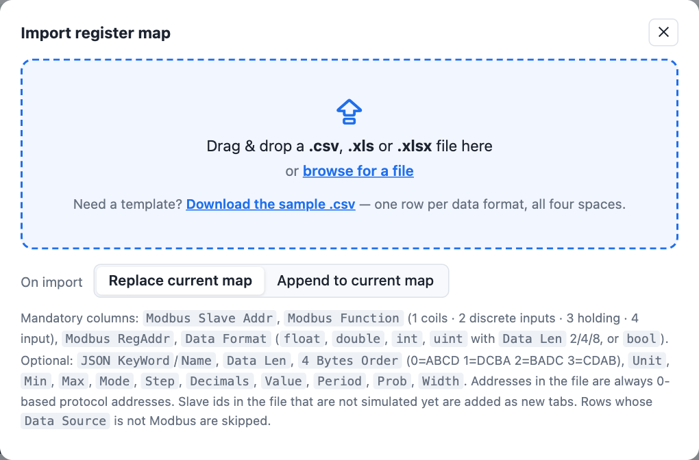
Instead of typing registers, upload the device's register list. The importer reads .csv, .xls and .xlsx files and fills all four spaces of the slave whose tab is open in one go.
Steps
- Open the tab of the slave the file belongs to and click Upload CSV / XLS above any table. The dialog title names that slave.
- Choose Replace current map to discard that slave's registers and load the file, or Append to current map to add the file's rows to them. Other slaves are never touched.
- Drop the file on the dotted box, or click it to browse. The import runs at once and the dialog closes; a message summarises how many rows were imported and lists any that were skipped with the reason.
File format
The first row holds column names. Names are matched loosely — case, spaces and punctuation are ignored — and the header may be preceded by a few title rows.
| Column | Required | Meaning |
|---|---|---|
Modbus Function | yes | The read function code: 1 coil, 2 discrete input, 3 holding register, 4 input register. |
Modbus RegAddr | yes | 0-based start address. |
Data Format | yes | float, double, int, uint, bool, or a simulator type name such as float32 or uint16. |
Data Len | no | Size in bytes: 2, 4 or 8. Decides between int16 / int32 / int64 and float32 / float64. Defaults: float → float32, int / uint → 16-bit. |
4 Bytes Order | no | Byte order: 0 or ABCD, 1 or DCBA, 2 or BADC, 3 or CDAB. |
JSON KeyWord or Name | no | Register name. |
Unit, Min, Max, Mode, Step, Decimals, Value | no | Simulation settings for registers, as in the table. |
Period, Prob, Width | no | Bit mode parameters in ms / 0–1 / ms. |
Data Source | no | If present, rows whose source does not contain "Modbus" are skipped. Useful for device export files that mix Modbus rows with others. |
Modbus Slave Addr | ignored | Many device files carry a slave-address column. It is ignored: every row goes into the slave you are uploading to. |
When Min, Max, Mode and Unit are missing, the importer guesses sensible values from the name: names containing volt get 228–232 V, curr 4–16 A, freq 49.95–50.05 Hz, power 1000–3000 W, energy an incrementing counter, THD 0.5–4 %.
Request log
The request log at the bottom of the page shows every frame the simulator receives, on every transport and for every slave, newest first.
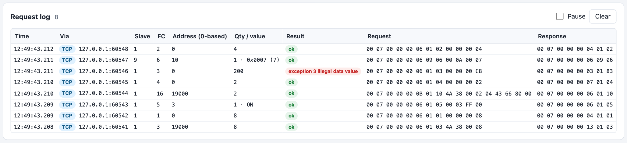
| Column | Meaning |
|---|---|
| Time | Arrival time with milliseconds. |
| Via | TCP with the client address and port, RTU or ASCII. |
| Slave | Unit id in the request. |
| FC | Function code; hover for its name. |
| Address, Qty / value | Start address (in the selected base) and quantity, or the written value for single writes, masks for FC22. |
| Result | ok · exception N with its name · ignored when the unit id is not served on that transport · broadcast for unit id 0 (processed, never answered) · bad-crc for corrupted RTU frames · bad-lrc for ASCII frames with a wrong checksum, invalid characters or an inter-character timeout. |
| Request, Response | The complete frames in hex, including the TCP header or the RTU CRC. Modbus ASCII frames are shown as the text that travelled on the line, for example :02034A38000277 (the trailing CR LF is not shown). |
Pause stops the list from scrolling while you read; Clear empties it. The last 300 requests are kept.
Function codes and exceptions
| FC | Name | Notes |
|---|---|---|
| 1 | Read Coils | 1–2000 bits per request |
| 2 | Read Discrete Inputs | 1–2000 bits |
| 3 | Read Holding Registers | 1–125 registers |
| 4 | Read Input Registers | 1–125 registers |
| 5 | Write Single Coil | value FF00 = on, 0000 = off |
| 6 | Write Single Register | |
| 7 | Read Exception Status | returns 0 (serial line) |
| 8 | Diagnostics | sub-function 0 (return query data) only |
| 15 | Write Multiple Coils | 1–1968 bits |
| 16 | Write Multiple Registers | 1–123 registers |
| 17 | Report Server ID | returns the slave id and a run indicator |
| 22 | Mask Write Register | (current AND and_mask) OR (or_mask AND NOT and_mask) |
| 23 | Read/Write Multiple Registers | write first, then read |
| 43 / 14 | Read Device Identification | vendor name, product code, revision (basic) plus vendor URL, product name, model name and application name (regular); stream and individual access, conformity level 0x82. The values are set per slave under Device identification. |
| Exception | Meaning | When the simulator sends it |
|---|---|---|
| 01 | Illegal function | Unsupported function code, write to a read-only space, diagnostics sub-function other than 0 |
| 02 | Illegal data address | Read or write touching an undefined address while the slave is set to reject it; address beyond 65535 |
| 03 | Illegal data value | Quantity out of range, byte count mismatch, coil value other than FF00/0000 |
Testing with a master
Modbus TCP
- Add a TCP slave. Note the address in the summary line, for example
192.168.0.81:502. - In the master, create a TCP connection to that IP and port, with unit id equal to the slave id.
- Poll, for example FC3 from address 19000 for 26 registers (13 floats). The request log shows each poll and the values are those in the table.
If the master is on another PC, allow the port through the Windows firewall when asked, or add a rule for the executable. The unit id in the master must equal the slave id; other ids are ignored.
Modbus RTU
- Plug in the USB-to-RS-485 adapter and install its driver if Windows does not recognise it. Note its COM port in Device Manager.
- Add an RTU slave with that port and the master's line settings, then Start it. The tab shows RTU listening on COMx.
- Wire A to A and B to B, and poll from the master with the slave id.
- No reply: swap A and B. bad-crc in the log: baud rate or parity mismatch. ignored: the master uses a different slave id.
Modbus ASCII
- Connect the adapter as for RTU. In the master, select the ASCII transmission mode and note its line settings — usually
9600 7E1. - Add a slave with protocol Modbus ASCII, the same port and line settings, then Start it. The tab shows ASCII listening on COMx.
- Poll from the master. The request log shows the frames as text, which makes them easy to compare with the master's own trace or with a serial terminal.
- bad-lrc in the log: line settings differ (7 versus 8 data bits is the usual cause) or the master is actually sending RTU. Nothing in the log at all: wiring, or the master is set to RTU and its binary frames contain no colon.
Command line and data folder
tamidas-modbus-simulator.exe                 start and open the browser
tamidas-modbus-simulator.exe --no-open       start without opening the browser
tamidas-modbus-simulator.exe --help          show the options

set PORT=9000 & tamidas-modbus-simulator.exe            web interface on another port
set MODBUS_SIM_DATA=D:\sim\data & tamidas-modbus-simulator.exe   use another data folder

macOS / Linux — the same options, from a terminal:
./tamidas-modbus-simulator-macos-arm64 --no-open
PORT=9000 ./tamidas-modbus-simulator-linux-x64
MODBUS_SIM_DATA=/opt/sim/data ./tamidas-modbus-simulator-linux-x64| Build | For |
|---|---|
tamidas-modbus-simulator.exe | Windows 10/11, 64-bit |
tamidas-modbus-simulator-macos-arm64 | Macs with Apple silicon (M1 and later) — portable binary |
tamidas-modbus-simulator-macos-x64 | Intel Macs — portable binary |
tamidas-modbus-simulator-<version>-macos-arm64.pkg | Apple silicon — installer package |
tamidas-modbus-simulator-<version>-macos-x64.pkg | Intel Macs — installer package |
tamidas-modbus-simulator-linux-x64 | 64-bit Linux on Intel/AMD (Ubuntu, Debian, Fedora, …) |
tamidas-modbus-simulator-linux-arm64 | 64-bit Linux on ARM (Raspberry Pi 4/5 with a 64-bit OS, ARM servers) |
.pkg, click through the installer (it asks for your Mac password, as every installer does), then open Terminal and type tamidas-modbus-simulator. The package is signed and notarised by Apple and carries its notarisation ticket, so it installs without any security prompt, even offline. The command is placed in /usr/local/bin; settings and register maps go to ~/Library/Application Support/tamidas-modbus-simulator. To remove it: sudo rm /usr/local/bin/tamidas-modbus-simulator.curl -fsSL https://raw.githubusercontent.com/TamidaSRepo/modbus-simulator/main/install.sh | sh, then start tamidas-modbus-simulator. If you unpacked the archive yourself, start the binary from Terminal (./tamidas-modbus-simulator-macos-arm64) or double-click it in Finder. The macOS builds are signed with the TamidaS Developer ID and notarised by Apple, so Gatekeeper lets them run; if macOS asks once whether to open a file downloaded from the internet, click Open. The first start needs an internet connection for that check. Use the arm64 build on Apple silicon and the x64 build on an Intel Mac.curl -fsSL https://raw.githubusercontent.com/TamidaSRepo/modbus-simulator/main/install.sh | sh. If you unpacked the archive yourself and the file is not executable, run chmod +x on it. To use a serial adapter without root, add yourself to the dialout group and log in again. TCP ports below 1024 (such as 502) need sudo setcap 'cap_net_bind_service=+ep' <binary> or a port such as 1502.| File | Content |
|---|---|
data/config.json | Slaves with their transport and simulation settings. |
data/registers.json | All registers and their current values. Saved on every change and every 30 s. |
Both files are plain JSON. Copy the data folder to move a setup to another PC, or keep several folders and point MODBUS_SIM_DATA at the one you need.
Troubleshooting
Windows shows a SmartScreen warning when starting the exe
The file is not code-signed. Choose More info → Run anyway. The program only runs locally and does not connect to the internet.
macOS says the app cannot be opened or the developer cannot be verified
The published builds are signed and notarised, so this should not happen with a file downloaded from this site. It appears when the download was damaged, when the Mac is offline during the first start (Gatekeeper fetches the notarisation ticket once), or when the file is not the original. Download the archive again and check its SHA-256 against SHA256SUMS, or use the installer script, which verifies the checksum for you. On an Intel Mac use the x64 build; on Apple silicon the arm64 build.
The settings are not next to the executable
When the folder holding the executable cannot be written (Homebrew, /usr/local/bin, Program Files, a .pkg install) the data folder moves to the user's application-data folder: ~/Library/Application Support/tamidas-modbus-simulator on macOS, ~/.local/share/tamidas-modbus-simulator on Linux, %APPDATA%\TamidaS\modbus-simulator on Windows. The console prints the folder in use at start; MODBUS_SIM_DATA overrides it.
On Linux the serial port cannot be opened ("permission denied")
Your user is not allowed to use the adapter. Add it to the dialout group (sudo usermod -aG dialout $USER), log out and in again, and Start the slave. The same applies to /dev/ttyACM0 devices.
The tab says "Port 502 is already in use"
Another program (or another slave with a different bind host) is listening on that port. Edit the slave and pick another port, or stop the other program.
The master times out on TCP
Check that the slave is live (green dot), that the master uses the address shown in the summary line, and that the Windows firewall allows the port. Requests that reach the simulator always appear in the log, so an empty log means the connection never arrived.
Values read by the master are wrong
Compare the master's raw registers with the Raw words column. If the words match but the value does not, change the byte order or data type. If the words differ, the master is reading a different address — remember 0- vs 1-based.
The master reads a block and gets exception 02
The block covers an address you have not defined and the slave's Read unmapped is set to Exception 02. Add the missing registers or switch the setting to Return 0.
A value I set keeps changing
The register is in random or increment mode. Set the mode to fixed, or type the value — typing sets fixed automatically.
A Modbus ASCII master gets no answer, or the log shows bad-lrc
Both ends must use the same mode and the same line settings. bad-lrc with readable text in the Request column usually means a data-bits or parity mismatch (the standard for ASCII is 7E1); unreadable text means the master is sending RTU frames to an ASCII slave. An RTU slave that receives ASCII frames logs bad-crc instead. Switch the slave's protocol in ✎ Edit slave — the serial port and register map are kept.
Auto-detect does not find my USB adapter
Auto-detect looks for common USB serial names at start time. Press ↻ in the port list, select the COM port explicitly and Start the slave again.
Where are the log and the settings after I closed the program?
Settings and registers are in the data folder next to the executable; the request log is not saved.